The cheme toolkit

A chemical plant, kept like a software project

cheme is an open command-line toolkit for chemical engineers. Every part of a design (the chemistry, the flowsheet, the drawings, the lists, the 3D plant, cost, safety and life cycle) is a plain file in a git repository. cheme checks that the files agree, simulates and draws from them, and tells you what is still missing.

The idea

A plant is a folder of files

Instead of drawings, spreadsheets and reports that drift apart, a plant lives in one folder. Everything in it is text that people and computers can read: YAML for data, DEXPI XML for the P&IDs, Markdown for the decisions. Git keeps every change, with who made it and why.

Engineers and AI agents work on the same files, and the same checks apply to both.

asu-1/
├─ plant.yaml        the project: name, stage, drawings
├─ process/          reactions, flowsheet, simulation, design basis
├─ pid/              P&IDs (DEXPI 2.0.1)
├─ equipment/        equipment list and datasheets
├─ layout/           the 3D plant model
├─ control/          loops, interlocks, sequences
├─ safety/           HAZOP studies, risk matrix
├─ estimate/  lca/   cost and life cycle
└─ DESIGN.md         decisions and assumptions
Chemistry and reaction engineering

It starts with the chemistry

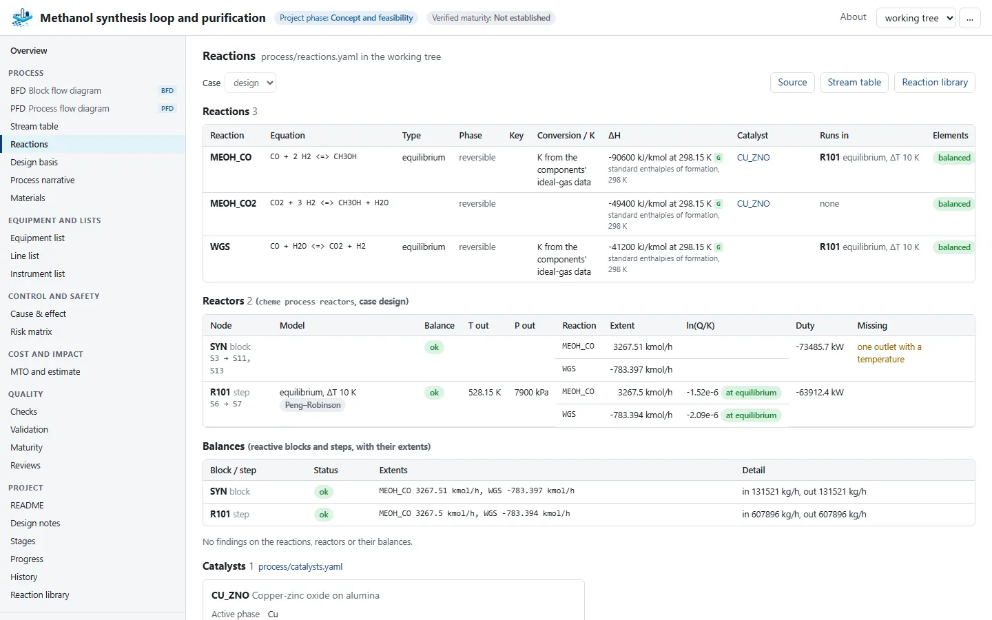
A design begins with the reactions. Each one is written down with its stoichiometry, which cheme checks for an element balance, and with what sets its extent: a conversion, a chemical equilibrium, or a rate law.

  • Catalysts with their composition, particle data and operating window
  • Kinetics fitted to laboratory data, with the uncertainty of each parameter
  • Reactor models, including temperature and pressure profiles along a catalyst bed
The reactions page of the methanol process in the Viewer: reactions with their equations, element balance and catalysts
Viewer · reactions of the methanol process

Process simulation

Simulate the whole process

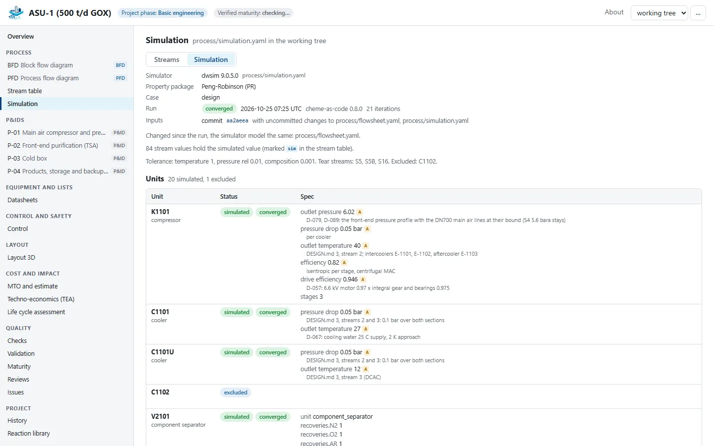
The flowsheet becomes a simulation model without retyping anything: cheme translates it for the open-source simulator DWSIM, solves it with its recycle loops, and writes the results back into the stream table.

Every simulated value is marked as such. When the flowsheet changes later, the results are flagged as out of date instead of silently kept.

The recorded simulation run of the air separation unit in the Viewer: converged streams and the units that were simulated
Viewer · the simulation run of the air separation unit

Drawings

Drawings generated, not drawn twice

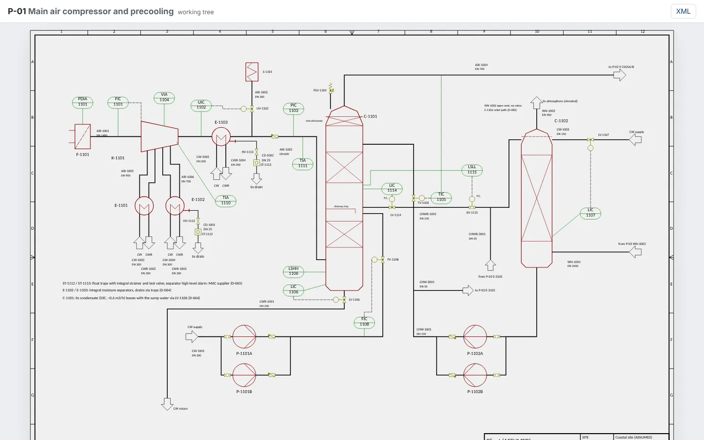
The block flow diagram and the process flow diagram are generated from the flowsheet. P&IDs are DEXPI 2.0.1, the open standard for piping and instrumentation diagrams. cheme renders them, formats them so a change stays a small readable diff, and shows what changed between two versions.

A P&ID of the main air compressor of the air separation unit, rendered from DEXPI XML
Viewer · P&ID P-01 of the air separation unit

Traceability

Every number says where it comes from

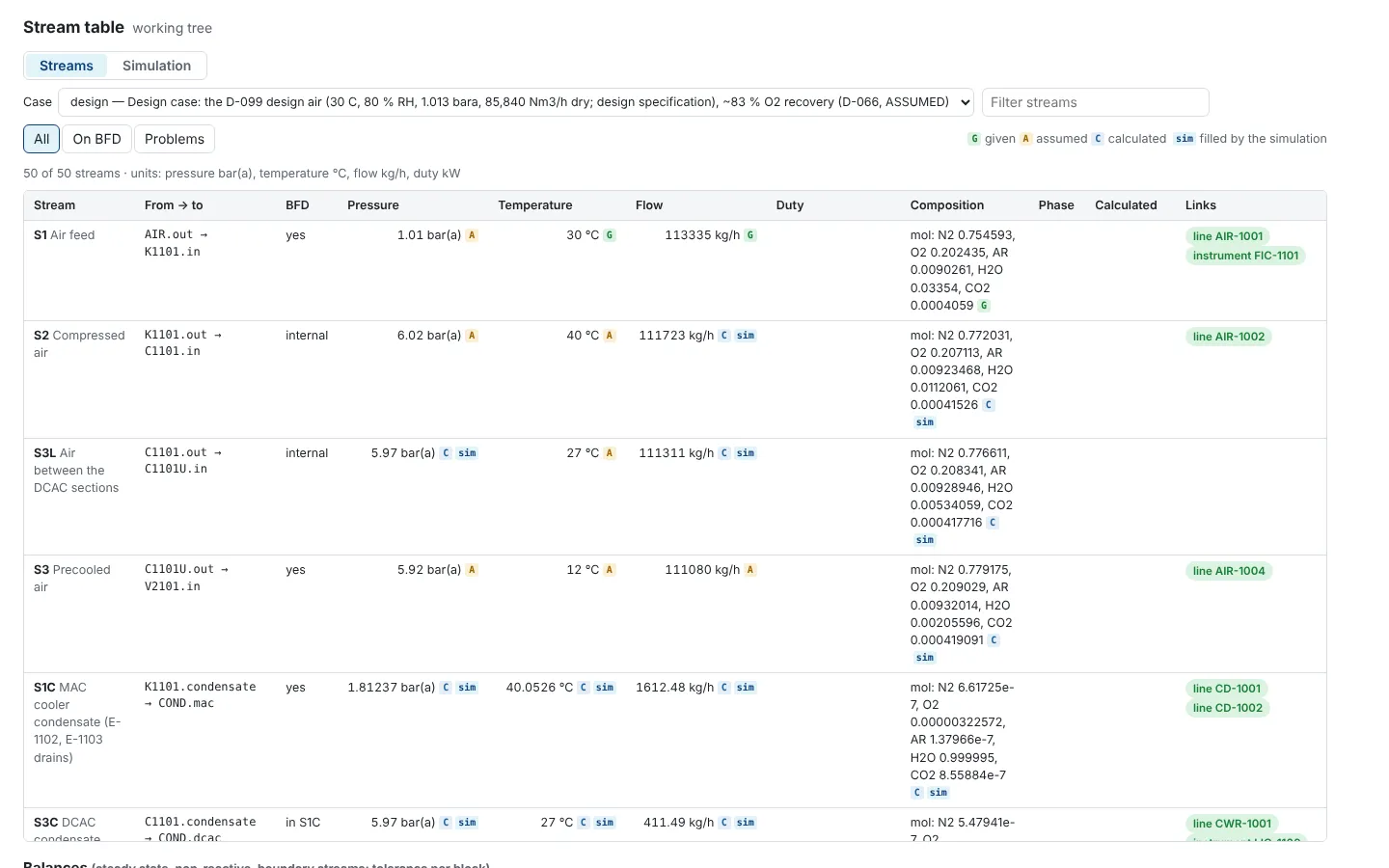
Each value is marked given (with its source), assumed (and says so), or calculated (and by what). Nobody has to guess whether a number was measured, estimated or simulated.

Stream table of the air separation unit: pressure, temperature, flow and composition, each marked given, assumed or calculated
Viewer · stream table

Basic and detail engineering

From the flowsheet to the plant

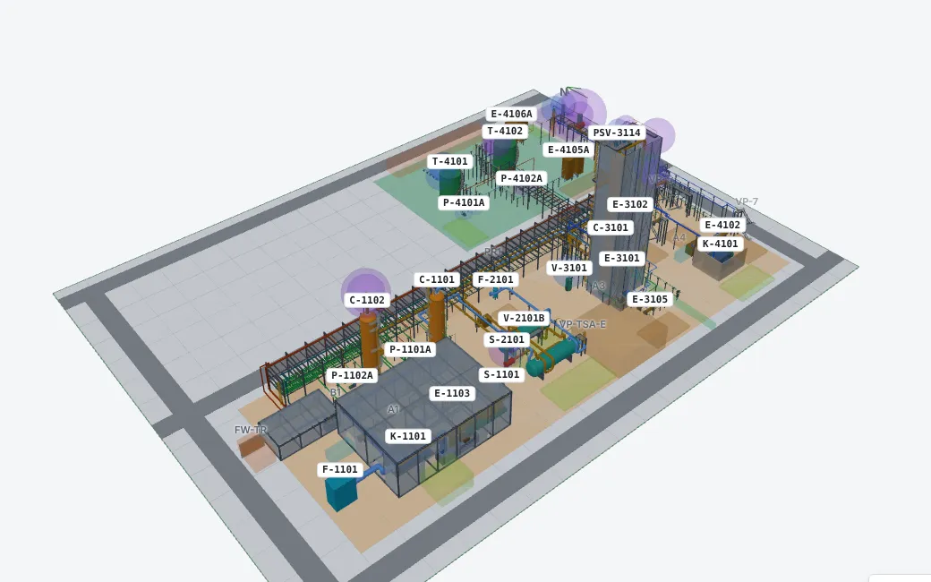
The same files carry the design on: equipment and line lists, sized equipment with datasheets, a 3D plant layout with routed pipes, steel and access, a material take-off counted from the model, and a cost estimate.

The 3D layout of the air separation unit with equipment, pipe racks and areas
Viewer · 3D layout

Safety and control

Safety and control from the same source

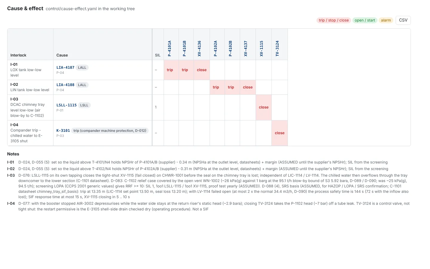
Interlocks become a cause and effect matrix. Control loops, operating sequences and the control philosophy are files too, as are HAZOP studies with their guide words, causes, safeguards and risk.

Cause and effect matrix of the air separation unit: interlocks and the equipment they trip
Viewer · cause and effect matrix

Quality

Checks and stages, like a design office

cheme validate finds what does not agree, down to the file and line. A project moves through the stages of an engineering project (concept, basic, detail), and each stage has gates that must pass before it is signed off.

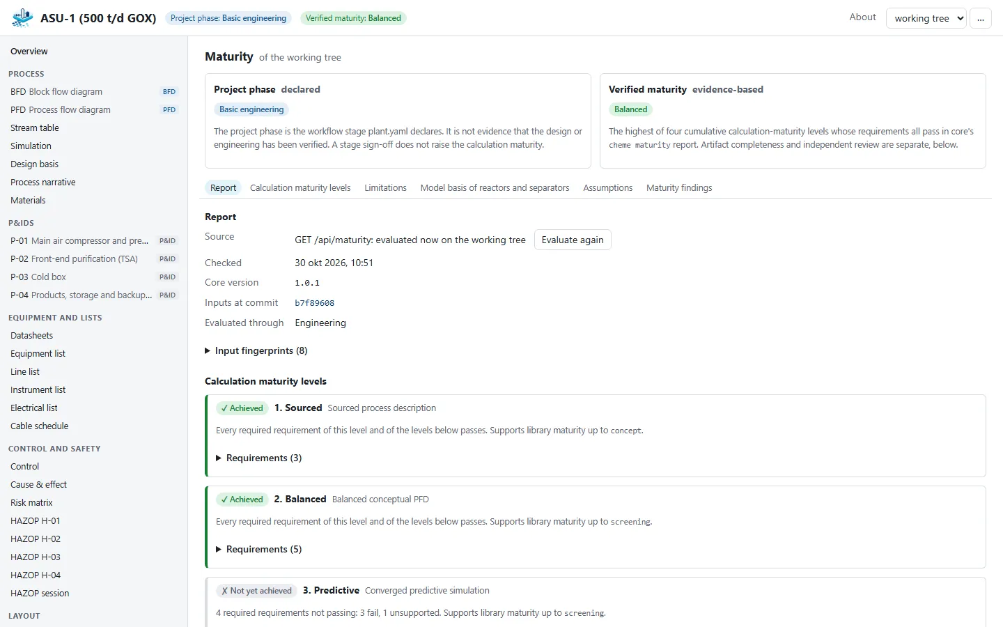
A separate, evidence-based maturity says how far the calculations really go, so a design never claims more than it shows.

The maturity page of the air separation unit: the calculation maturity levels and their requirements
Viewer · calculation maturity

Life cycle

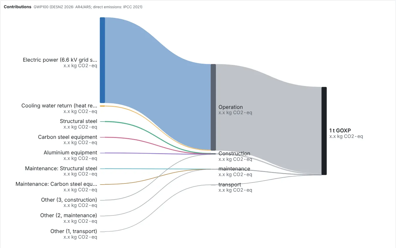
Life cycle assessment from the design

The inventory for a life cycle assessment comes from the same stream table, linked to background data and exported as open inventories for Brightway and openLCA, so the footprint follows the design as it changes.

Sankey diagram of the life-cycle contributions of the air separation unit (values not shown)
Viewer · life cycle assessment (values hidden here)

Go further